Address
Compaero India (P) Ltd.
No. 41/773- A to A3,
RC Arcade, Ideal Lane, NH Bypass,
Padivattom, Edappally, Kochi
Ernakulam,
Kerala 682 024, India
Compaero India (P) Ltd.
No. 41/773- A to A3,
RC Arcade, Ideal Lane, NH Bypass,
Padivattom, Edappally, Kochi
Ernakulam,
Kerala 682 024, India

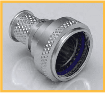
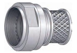
Compaero manufacture and supply an extensive range of circular backshells to suit harsh environments across land, sea and air. Available solutions can provide both environmental and non-environmental sealing capabilities, effective EMI and RFI shielding and impressive strain relief options for almost any application.
Standard range circular backshells can be customized from a huge selection of options to ensure that your Compaero product is fully fit for purpose, whilst our team of experienced design engineers are on hand to work with you to provide bespoke solutions for more specific needs.
Shrink Boot Adapter Environmental, Non-Screened
EMI/RFI Lamp Base Thread Environmental, Screened
Shield Sock Shrink Boot Adapter, Environmental Screened
Banding Adapter
EMI/RFI Shrink Boot Bandstrap Adapter, Environmental, Screened
EMI/RFI Memory Ring Shrink Boot Adapter, Environmental, Screened
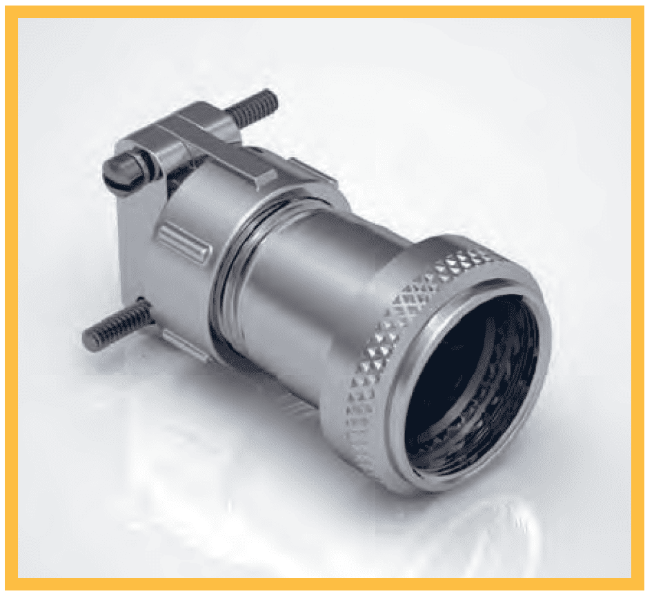
Cable Clamp Adapter Non-Environmental, Non-Screened
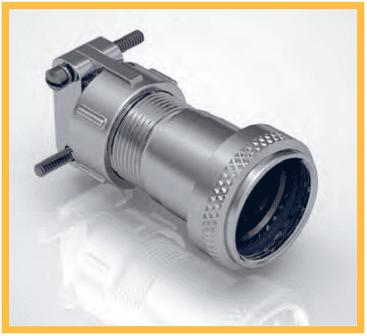
Submersible Cable Clamp Adapter, Environmental, Non-Screened
Non-Submersible Cable Clamp Adapter, Environmental, Non-Screened
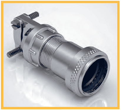
EMI/RFI Cable Clamp Adapter, Non-Environmental, Screened
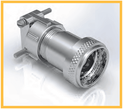
EMI/RFI Cable Clamp Adapter, Non-Environmental, Screened
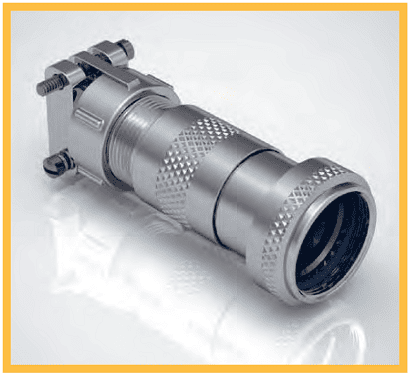
Submersible EMI/RFI Cable Clamp Adapter, Environmental, Screened
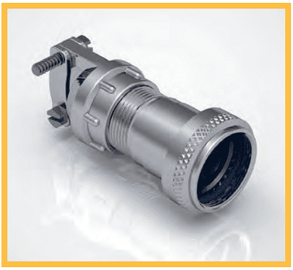
Non-Submersible EMI/RFI Cable Clamp Adapter, Environmental, Screened
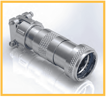
Submersible EMI/RFI Cable Clamp Adapter, Environmental, Screened
Use the table below to identify the correct Series based on your required termination style, screening options, and strain relief needs.
| Series | Termination Style | Screening Options | Strain Relief & Cable Sealing | Required Components | ||||
|---|---|---|---|---|---|---|---|---|
| Individual (Inner/Outer) | Overall (Outer) | Reworkable Tool Free | Heat Shrink Boot | Cable Clamp | Boot / Band | Compression Spring / Grommet | ||
| ENVIRONMENTAL | ||||||||
| SERIES 30 | Heat Shrink Boot | N/A | N/A | |||||
| SERIES 31 | Lamp Base Thread | |||||||
| SERIES 35 | Shield Sock | |||||||
| SERIES 43 | Cable Sealing Band In A Can | * | ||||||
| SERIES 45 | Band/Spring | |||||||
| SERIES 42 | Band | |||||||
| SERIES 46 | Band/Spring | |||||||
| SERIES 49 | Memory Ring | |||||||
| SERIES 60 | Cable Clamp, Environmental | N/A | N/A | |||||
| SERIES 61 | Cable Clamp, Environmental | N/A | N/A | |||||
| SERIES 62 | Cable Clamp, Splash-Proof | N/A | N/A | |||||
| SERIES 80 | Cone Clamp, Environmental | |||||||
| SERIES 81 | Cone Clamp, Environmental | |||||||
| SERIES 82 | Cone Clamp, Environmental | |||||||
| SERIES 83 | Cone Clamp, Environmental | |||||||
| SERIES 84 | Cone Clamp, Environmental | |||||||
| SERIES 85 | Cone Clamp, Splash-Proof | |||||||
| SERIES 86 | Cone Clamp, Environmental | |||||||
| SERIES 87 | Cone Clamp, Environmental | |||||||
| SERIES 88 | Cone Clamp, Environmental | |||||||
| SERIES 89 | Cone Clamp, Environmental | |||||||
| NON-ENVIRONMENTAL | ||||||||
| SERIES 40 | Band/Spring | * | ||||||
| SERIES 55 | Cable Clamp, Non-Environmental | N/A | N/A | |||||
| SERIES 70 | Cone Clamp, Non-Environmental | |||||||
| SERIES 71 | Cone Clamp, Non-Environmental | |||||||
| SERIES 72 | Cone Clamp, Non-Environmental | |||||||
| SERIES 73 | Cone Clamp, Non-Environmental | |||||||
| SERIES 74 | Cone Clamp, Non-Environmental | |||||||
| SERIES 75 | Cone Clamp, Non-Environmental | |||||||
| SERIES 76 | Cone Clamp, Non-Environmental | |||||||
| SERIES 77 | Cone Clamp, Non-Environmental | |||||||
Compaero offer termination solutions for virtually all known connector interfaces, the variants highlighted below are our standard lines, available on all product lines.
| CONNECTOR INTERFACE | INTERFACE CODE |
|---|---|
| EN2997, ESC10, ESC11 | A |
| EN3645 | H |
|
MIL-DTL-26482 SERIES I SOLDER MS3110, MS3116 WITHOUT ACCESSORY TEETH |
DK |
|
MIL-DTL-26482 SERIES II MS3470, MS3471, MS3472, MS3474, MS3475, MS3476 |
A |
|
MIL-DTL-38999 SERIES I & II MS27466-68, MS27472-74, MS27479-81, MS27484, MS27497, MS27652, MS27653, MS27656 |
F |
|
MIL-DTL-38999 SERIES III & IV D38999/20, /24, /26, /40, /46, /47 |
H |
|
MIL-DTL-5015 SOLDER MS3100, MS3101, MS3106, Amphenol Class A (Blue Insert) |
BA |
|
MIL-DTL-5015 SOLDER MS3100, MS3101, MS3106, Bendix - Class A, E & R |
BB |
|
MIL-DTL-5015 SOLDER MS3100, MS3101, MS3106, Cannon - Class A, E & R |
BC |
|
MIL-DTL-5015 SOLDER MS3100, MS3101, MS3106, Amphenol - Class R (Resilient Insert) |
BR |
|
MIL-DTL-5015 CRIMP MS3400, MS3401, MS3404, MS3406, MS3450, MS3451, MS3454, MS3456 |
A |
|
MIL-DTL-83723 SERIES I & III M83723/1/8/13/,14./36-/43/,48/49/65-/78/82-187, 191, 192, 195, 197, 198 |
A |
|
BS9522 F0017 PATT 105 AMPHENOL 62GB |
VA |
|
VG95234 / BS9522 F0032 PATT 121B ABCIR RANGE |
VB |
| ADAPTER SHELL SIZE |
CONNECTOR SHELL SIZE |
A THREAD | ØB MAX in / mm |
C MAX in / mm |
D MAX in / mm |
E MAX in / mm |
MAX ENTRY |
|---|---|---|---|---|---|---|---|
| 08 | 8S | 7/16-27UNS | 0.75 19.2 | 0.59 15.0 | 0.72 18.3 | 1.02 25.9 | 32 |
| 10 | 10S | 1/2-28UNEF | 0.82 20.8 | 0.60 15.4 | 0.75 19.1 | 1.08 27.5 | 03 |
| 11 | 10SL | 5/8-24UNEF | 0.94 23.9 | 0.63 16.0 | 0.81 20.7 | 1.21 30.6 | 04 |
| 12 | 12, 12S | 11/16-24UNEF | 1.02 25.9 | 0.64 16.3 | 0.84 21.5 | 1.27 32.2 | 34 |
| 14 | 14, 14S | 3/4-20UNEF | 1.08 27.5 | 0.66 16.7 | 0.88 22.2 | 1.33 33.8 | 05 |
| 16 | 16, 16S | 7/8-20UNEF | 1.27 32.3 | 0.71 18.1 | 0.97 24.6 | 1.49 37.8 | 06 |
| 18 | 18 | 1-20UNEF | 1.40 35.4 | 0.74 18.8 | 1.03 26.2 | 1.61 40.9 | 36 |
| 20 | 20 | 1 1/8-18UNEF | 1.52 38.6 | 0.77 19.4 | 1.09 27.8 | 1.74 44.1 | 08 |
| 22 | 22 | 1 1/4-18UNEF | 1.65 41.8 | 0.79 20.1 | 1.16 29.4 | 1.86 47.3 | 09 |
| 24 | 24 | 1 3/8-18UNEF | 1.85 46.9 | 0.85 21.5 | 1.25 31.8 | 2.02 51.3 | 10 |
| 28 | 28 | 1 5/8-18UNEF | 1.97 50.1 | 0.87 22.2 | 1.31 33.4 | 2.14 54.4 | 11 |
| 32 | 32 | 1 29/32-18UN | 2.22 56.4 | 0.93 23.5 | 1.44 36.5 | 2.39 60.8 | 13 |
| 36 | 36 | 2 1/8-18UNS | 2.55 64.8 | 1.01 25.6 | 1.59 40.5 | 2.67 67.9 | 15 |
| 40 | 40 | 2 3/8-16UN | 2.80 71.2 | 1.06 26.9 | 1.72 43.7 | 2.92 74.3 | - |
| 44 | 44 | 2 5/8-16UN | 3.05 77.5 | 1.11 28.3 | 1.84 46.9 | 3.17 80.6 | - |
| 48 | 48 | 2 7/8-16UN | 3.38 85.9 | 1.20 30.4 | 2.00 50.8 | 3.46 87.8 | - |
| ADAPTER SHELL SIZE |
CONNECTOR SHELL SIZE |
A THREAD | ØB MAX in / mm |
C MAX in / mm |
D MAX in / mm |
E MAX in / mm |
MAX ENTRY |
|---|---|---|---|---|---|---|---|
| 08 | 8S | 7/16-28UNEF | 0.75 19.2 | 0.59 15.0 | 0.72 18.3 | 1.02 25.9 | 32 |
| 10 | 10S | 1/2-28UNEF | 0.82 20.8 | 0.60 15.4 | 0.75 19.1 | 1.08 27.5 | 03 |
| 11 | 10SL | 9/16-24UNEF | 0.88 22.3 | 0.62 15.7 | 0.78 19.9 | 1.14 29.0 | 33 |
| 12 | 12, 12S | 5/8-24UNEF | 0.94 23.9 | 0.63 16.0 | 0.81 20.7 | 1.21 30.6 | 04 |
| 14 | 14, 14S | 3/4-20UNEF | 1.08 27.5 | 0.66 16.7 | 0.88 22.2 | 1.33 33.8 | 34 |
| 16 | 16, 16S | 7/8-20UNEF | 1.27 32.3 | 0.71 18.1 | 0.97 24.6 | 1.49 37.8 | 35 |
| 18 | 18 | 1-20UNEF | 1.40 35.4 | 0.74 18.8 | 1.03 26.2 | 1.61 40.9 | 36 |
| 20 | 20 | 1 1/8-18UNEF | 1.52 38.6 | 0.77 19.4 | 1.09 27.8 | 1.74 44.1 | 37 |
| 22 | 22 | 1 1/4-18UNEF | 1.65 41.8 | 0.79 20.1 | 1.16 29.4 | 1.86 47.3 | 38 |
| 24 | 24 | 1 3/8-18UNEF | 1.85 46.9 | 0.85 21.5 | 1.25 31.8 | 2.02 51.3 | 09 |
| 28 | 28 | 1 5/8-18UNEF | 1.97 50.1 | 0.87 22.2 | 1.31 33.4 | 2.14 54.4 | 11 |
| 32 | 32 | 1 7/8-16UN | 2.22 56.4 | 0.93 23.5 | 1.44 36.5 | 2.39 60.8 | 13 |
| 36 | 36 | 2 1/8-16UN | 2.55 64.8 | 1.01 25.6 | 1.59 40.5 | 2.67 67.9 | 15 |
| 40 | 40 | 2 3/8-16UN | 2.80 71.2 | 1.06 26.9 | 1.72 43.7 | 2.92 74.3 | - |
| 44 | 44 | 2 5/8-16UN | 3.05 77.5 | 1.11 28.3 | 1.84 46.9 | 3.17 80.6 | - |
| 48 | 48 | 2 13/16-18UNS | 3.38 85.9 | 1.20 30.4 | 2.00 50.8 | 3.46 87.8 | - |
| ADAPTER SHELL SIZE |
CONNECTOR SHELL SIZE |
A THREAD | ØB MAX in / mm |
C MAX in / mm |
D MAX in / mm |
E MAX in / mm |
MAX ENTRY |
|---|---|---|---|---|---|---|---|
| 08 | 8S | 7/16-27UNS | 0.75 19.2 | 0.59 15.0 | 0.72 18.3 | 1.02 25.9 | 32 |
| 10 | 10S | 1/2-28UNEF | 0.82 20.8 | 0.60 15.4 | 0.75 19.1 | 1.08 27.5 | 03 |
| 11 | 10SL | 5/8-24UNEF | 0.94 23.9 | 0.63 16.0 | 0.81 20.7 | 1.21 30.6 | 04 |
| 12 | 12, 12S | 11/16-24UNEF | 1.02 25.9 | 0.64 16.3 | 0.84 21.5 | 1.27 32.2 | 34 |
| 14 | 14, 14S | 3/4-20UNEF | 1.08 27.5 | 0.66 16.7 | 0.88 22.2 | 1.33 33.8 | 05 |
| 16 | 16, 16S | 7/8-20UNEF | 1.27 32.3 | 0.71 18.1 | 0.97 24.6 | 1.49 37.8 | 06 |
| 18 | 18 | 1-20UNEF | 1.40 35.4 | 0.74 18.8 | 1.03 26.2 | 1.61 40.9 | 36 |
| 20 | 20 | 1 1/8-24UNS | 1.52 38.6 | 0.77 19.4 | 1.09 27.8 | 1.74 44.1 | 08 |
| 22 | 22 | 1 1/4-18UNEF | 1.65 41.8 | 0.79 20.1 | 1.16 29.4 | 1.86 47.3 | 09 |
| 24 | 24 | 1 3/8-18UNEF | 1.85 46.9 | 0.85 21.5 | 1.25 31.8 | 2.02 51.3 | 10 |
| 28 | 28 | 1 5/8-18UNEF | 1.97 50.1 | 0.87 22.2 | 1.31 33.4 | 2.14 54.4 | 11 |
| 32 | 32 | 1 29/32-18UN | 2.22 56.4 | 0.93 23.5 | 1.44 36.5 | 2.39 60.8 | 13 |
| 36 | 36 | 2 1/16-20UNS | 2.55 64.8 | 1.01 25.6 | 1.59 40.5 | 2.67 67.9 | 15 |
| 40 | 40 | 2 3/8-16UN | 2.80 71.2 | 1.06 26.9 | 1.72 43.7 | 2.92 74.3 | - |
| 44 | 44 | 2 5/8-16UN | 3.05 77.5 | 1.11 28.3 | 1.84 46.9 | 3.17 80.6 | - |
| 48 | 48 | 2 7/8-16UN | 3.38 85.9 | 1.20 30.4 | 2.00 50.8 | 3.46 87.8 | - |
| ADAPTER SHELL SIZE |
CONNECTOR SHELL SIZE |
A THREAD | ØB MAX in / mm |
C MAX in / mm |
D MAX in / mm |
E MAX in / mm |
MAX ENTRY |
|---|---|---|---|---|---|---|---|
| 08 | 8S | 3/8-32UNEF | 0.69 17.6 | 0.58 14.7 | 0.69 17.5 | 0.96 24.3 | 02 |
| 10 | 10S | 1/2-28UNEF | 0.82 20.8 | 0.60 15.4 | 0.75 19.1 | 1.08 27.5 | 03 |
| 11 | 10SL | 5/8-24UNEF | 0.94 23.9 | 0.63 16.0 | 0.81 20.7 | 1.21 30.6 | 04 |
| 12 | 12, 12S | 5/8-24UNEF | 0.94 23.9 | 0.63 16.0 | 0.81 20.7 | 1.21 30.6 | 04 |
| 14 | 14, 14S | 3/4-20UNEF | 1.08 27.5 | 0.66 16.7 | 0.88 22.2 | 1.33 33.8 | 05 |
| 16 | 16, 16S | 7/8-20UNEF | 1.27 32.3 | 0.71 18.1 | 0.97 24.6 | 1.49 37.8 | 06 |
| 18 | 18 | 1-20UNEF | 1.40 35.4 | 0.74 18.8 | 1.03 26.2 | 1.61 40.9 | 36 |
| 20 | 20 | 1 1/8-18UNEF | 1.52 38.6 | 0.77 19.4 | 1.09 27.8 | 1.74 44.1 | 08 |
| 22 | 22 | 1 1/4-18UNEF | 1.65 41.8 | 0.79 20.1 | 1.16 29.4 | 1.86 47.3 | 09 |
| 24 | 24 | 1 3/8-18UNEF | 1.85 46.9 | 0.85 21.5 | 1.25 31.8 | 2.02 51.3 | 10 |
| 28 | 28 | 1 5/8-18UNEF | 1.97 50.1 | 0.87 22.2 | 1.31 33.4 | 2.14 54.4 | 11 |
| 32 | 32 | 1 7/8-16UN | 2.22 56.4 | 0.93 23.5 | 1.44 36.5 | 2.39 60.8 | 13 |
| 36 | 36 | 2 1/16-16UNS | 2.55 64.8 | 1.01 25.6 | 1.59 40.5 | 2.67 67.9 | 15 |
| 40 | 40 | 2 5/16-16UNS | 2.80 71.2 | 1.06 26.9 | 1.72 43.7 | 2.92 74.3 | - |
| 44 | 44 | 2 5/8-16UN | 3.05 77.5 | 1.11 28.3 | 1.84 46.9 | 3.17 80.6 | - |
| SHELL SIZE |
A THREAD | ØB MAX in / mm |
C MAX in / mm |
D MAX in / mm |
E MAX in / mm |
MAX ENTRY |
|---|---|---|---|---|---|---|
| 08 | 1/2-20 UNF | 0.69 17.6 | 0.54 13.6 | 0.65 16.5 | 0.92 23.4 | 02 |
| 10 | 5/8-24 UNEF | 0.81 20.5 | 0.57 14.4 | 0.70 17.9 | 1.03 26.3 | 03 |
| 12 | 3/4-20 UNEF | 0.94 24.0 | 0.58 14.8 | 0.77 19.6 | 1.16 29.4 | 04 |
| 14 | 7/8-20 UNEF | 1.07 27.1 | 0.60 15.3 | 0.84 21.4 | 1.22 30.9 | 34 |
| 16 | 1-20 UNEF | 1.24 31.6 | 0.63 15.9 | 0.90 22.9 | 1.34 34.1 | 35 |
| 18 | 1 1/16-18 UNEF | 1.32 33.4 | 0.64 16.4 | 0.93 23.6 | 1.40 35.4 | 06 |
| 20 | 1 3/16-18 UNEF | 1.44 36.6 | 0.67 17.0 | 0.99 25.2 | 1.52 38.6 | 07 |
| 22 | 1 5/16-18 UNEF | 1.57 39.8 | 0.70 17.7 | 1.06 26.8 | 1.65 41.8 | 08 |
| 24 | 1 7/16-18 UNEF | 1.69 43.0 | 0.73 18.5 | 1.12 28.4 | 1.77 45.0 | 09 |
| 28 | 1 3/4-18 UNS | 2.00 50.9 | 0.83 21.2 | 1.28 32.6 | 2.06 52.4 | 11 |
| 32 | 2-18 UNS | 2.25 57.2 | 0.89 22.6 | 1.41 35.8 | 2.31 58.7 | 13 |
| 36 | 2 1/4-16 UN | 2.50 63.6 | 0.93 23.7 | 1.53 39.0 | 2.53 64.3 | 14 |
| 40 | 2 1/2-16 UN | 2.75 69.9 | 1.01 25.6 | 1.66 42.1 | 2.78 70.6 | 16 |
| 44 | 2 3/4-16UN | 3.00 76.3 | 1.06 26.9 | 1.78 45.3 | 3.03 77.0 | - |
| 48 | 3-16UN | 3.25 82.6 | 1.11 28.2 | 1.91 48.5 | 3.28 83.3 | - |
| 61 | 1 1/2-18UNEF | 1.75 44.5 | 0.77 19.4 | 1.16 29.4 | 1.84 46.8 | 09 |
| SHELL SIZE |
A THREAD | ØB MAX in / mm |
C MAX in / mm |
D MAX in / mm |
E MAX in / mm |
MAX ENTRY |
|---|---|---|---|---|---|---|
| 11 | 3/4-20UNEF | 1.04 26.5 | 0.80 20.4 | 0.95 24.1 | 1.28 32.5 | 03 |
| 13 | 7/8-20UNEF | 1.17 29.7 | 0.83 21.0 | 1.01 25.7 | 1.40 35.6 | 04 |
| 15 | 1-20UNEF | 1.23 31.3 | 0.85 21.7 | 1.07 27.2 | 1.53 38.8 | 05 |
| 17 | 1 1/8-18UNEF | 1.40 35.5 | 0.88 22.3 | 1.14 28.8 | 1.65 42.0 | 06 |
| 19 | 1 1/4-18UNEF | 1.52 38.7 | 0.90 23.0 | 1.20 30.4 | 1.78 45.2 | 07 |
| 23 | 1 7/16-18UNEF | 1.72 43.6 | 0.94 24.0 | 1.29 32.8 | 1.97 49.9 | 38 |
| 25 | 1 9/16-18UNEF | 1.86 47.2 | 0.97 24.6 | 1.35 34.4 | 2.09 53.1 | 09 |
| 29 | 1 7/8-16UN | 2.17 55.2 | 1.02 25.9 | 1.48 37.6 | 2.34 59.4 | 11 |
| 33 | 2 1/16-16UNS | 2.38 60.5 | 1.06 26.9 | 1.57 39.9 | 2.53 64.2 | 13 |
| SHELL SIZE |
A THREAD | ØB MAX in / mm |
C MAX in / mm |
D MAX in / mm |
E MAX in / mm |
MAX ENTRY |
|---|---|---|---|---|---|---|
| 09 | M12x1.0 | 0.74 18.7 | 0.42 10.6 | 0.62 15.7 | 0.84 21.2 | 32 |
| 11 | M15x1.0 | 0.86 21.9 | 0.44 11.2 | 0.68 17.2 | 0.96 24.3 | 33 |
| 13 | M18x1.0 | 1.01 25.6 | 0.49 12.3 | 0.76 19.2 | 1.10 27.9 | 34 |
| 15 | M22x1.0 | 1.13 28.8 | 0.51 13.0 | 0.82 20.8 | 1.23 31.1 | 35 |
| 17 | M25x1.0 | 1.26 32.0 | 0.55 13.9 | 0.89 22.6 | 1.36 34.5 | 36 |
| 19 | M28x1.0 | 1.39 35.2 | 0.57 14.6 | 0.95 24.2 | 1.45 36.9 | 07 |
| 21 | M31x1.0 | 1.51 38.4 | 0.60 15.3 | 1.02 25.8 | 1.58 40.1 | 08 |
| 23 | M34x1.0 | 1.64 41.6 | 0.63 15.9 | 1.08 27.4 | 1.71 43.3 | 09 |
| 25 | M37x1.0 | 1.78 45.2 | 0.65 16.6 | 1.14 29.0 | 1.83 46.5 | 10 |
| SHELL SIZE |
A THREAD | ØB MAX in / mm |
C MAX in / mm |
D MAX in / mm |
E MAX in / mm |
MAX ENTRY |
|---|---|---|---|---|---|---|
| 08 | 7/16-28UNEF | 0.66 16.8 | 0.50 12.7 | 0.60 15.3 | 0.87 22.1 | 02 |
| 10 | 9/16-24UNEF | 0.80 20.3 | 0.52 13.3 | 0.67 16.9 | 1.00 25.3 | 03 |
| 12 | 11/16-24UNEF | 0.92 23.4 | 0.55 13.9 | 0.73 18.5 | 1.12 28.4 | 04 |
| 14 | 13/16-20UNEF | 1.06 26.8 | 0.58 14.7 | 0.79 20.1 | 1.25 31.6 | 05 |
| 16 | 15/16-20UNEF | 1.18 30.0 | 0.60 15.4 | 0.85 21.7 | 1.37 34.8 | 06 |
| 18 | 1 1/16-18UNEF | 1.31 33.3 | 0.61 15.4 | 0.92 23.2 | 1.50 38.0 | 07 |
| 20 | 1 3/16-18UNEF | 1.44 36.5 | 0.66 16.7 | 0.98 24.8 | 1.62 41.1 | 08 |
| 22 | 1 5/16-18UNEF | 1.56 39.7 | 0.68 17.4 | 1.04 26.4 | 1.75 44.3 | 09 |
| 24 | 1 7/16-18UNEF | 1.69 42.9 | 0.68 17.4 | 1.10 28.0 | 1.87 47.5 | 10 |
| SHELL SIZE |
A THREAD | ØB MAX in / mm |
C MAX in / mm |
D MAX in / mm |
E MAX in / mm |
MAX ENTRY |
|---|---|---|---|---|---|---|
| 08 | 7/16-28UNEF | 0.68 17.3 | 0.57 14.4 | 0.72 18.2 | 1.00 25.5 | 02 |
| 10 | 9/16-24UNEF | 0.80 20.3 | 0.59 14.9 | 0.86 21.8 | 1.16 29.5 | 03 |
| 12 | 11/16-24UNEF | 0.94 23.8 | 0.62 15.7 | 0.83 21.0 | 1.26 32.0 | 04 |
| 14 | 13/16-20UNEF | 1.06 26.8 | 0.65 16.5 | 0.92 23.4 | 1.40 35.5 | 05 |
| 16 | 15/16-20UNEF | 1.17 29.8 | 0.66 16.8 | 0.96 24.5 | 1.52 38.5 | 06 |
| 18 | 1 1/16-18UNEF | 1.31 33.3 | 0.70 17.8 | 1.04 26.5 | 1.65 42.0 | 07 |
| 20 | 1 3/16-18UNEF | 1.43 36.3 | 0.71 18.1 | 1.12 28.5 | 1.79 45.5 | 08 |
| 22 | 1 5/16-18UNEF | 1.57 39.5 | 0.73 18.5 | 1.18 30.0 | 1.91 48.5 | 09 |
| 24 | 1 7/16-18UNEF | 1.69 42.8 | 0.78 19.7 | 1.24 31.5 | 2.03 51.5 | 10 |
| SHELL SIZE |
A THREAD | ØB MAX in / mm |
C MAX in / mm |
D MAX in / mm |
E MAX in / mm |
MAX ENTRY |
|---|---|---|---|---|---|---|
| 08 | 7/16-28UNEF | 0.68 17.3 | 0.57 14.4 | 0.72 18.2 | 1.00 25.5 | 02 |
| 10 | 9/16-24UNEF | 0.80 20.3 | 0.59 14.9 | 0.77 19.6 | 1.12 28.5 | 03 |
| 12 | 11/16-24UNEF | 0.94 23.8 | 0.62 15.7 | 0.83 21.0 | 1.26 32.0 | 04 |
| 14 | 13/16-20UNEF | 1.06 26.8 | 0.65 16.5 | 0.92 23.4 | 1.40 35.5 | 05 |
| 16 | 15/16-20UNEF | 1.17 29.8 | 0.66 16.8 | 0.96 24.5 | 1.52 38.5 | 06 |
| 18 | 1 1/16-18UNEF | 1.31 33.3 | 0.70 17.8 | 1.04 26.5 | 1.65 42.0 | 07 |
| 20 | 1 3/16-18UNEF | 1.43 36.3 | 0.71 18.1 | 1.12 28.5 | 1.79 45.5 | 08 |
| 22 | 1 5/16-18UNEF | 1.57 39.8 | 0.73 18.5 | 1.18 30.0 | 1.91 48.5 | 09 |
| 24 | 1 7/16-18UNEF | 1.69 42.8 | 0.78 19.7 | 1.22 31.0 | 2.03 51.5 | 10 |
| SHELL SIZE |
A THREAD | ØB MAX in / mm |
C MAX in / mm |
D MAX in / mm |
E MAX in / mm |
MAX ENTRY |
|---|---|---|---|---|---|---|
| 12 | 5/8-24UNEF | 0.80 20.3 | 0.68 17.3 | 0.83 21.1 | 1.16 29.4 | 03 |
| 14 | 3/4-20UNEF | 0.93 23.7 | 0.70 17.7 | 0.86 21.9 | 1.22 31.0 | 33 |
| 16 | 7/8-20UNEF | 1.05 26.7 | 1.00 25.3 | 1.20 30.4 | 1.62 41.2 | 34 |
| 18 | 1-20UNEF | 1.19 30.3 | 1.01 25.7 | 1.23 31.2 | 1.68 42.8 | 05 |
| 20 | 1 1/8-18UNEF | 1.39 35.3 | 1.04 26.3 | 1.29 32.8 | 1.81 46.0 | 06 |
| 22 | 1 1/4-18UNEF | 1.51 38.3 | 1.06 27.0 | 1.35 34.4 | 1.93 49.1 | 07 |
| 24 | 1 3/8-18UNEF | 1.63 41.3 | 1.09 27.6 | 1.42 36.0 | 2.06 52.3 | 08 |
| 28 | 1 5/8-18UNEF | 1.88 47.8 | 1.13 28.6 | 1.51 38.4 | 2.25 57.1 | 09 |
| 32 | 1 7/8-16UN | 2.13 54.2 | 1.18 29.9 | 1.64 41.5 | 2.50 63.4 | 11 |
| 36 | 2 1/16-16UNS | 2.45 62.2 | 1.22 30.9 | 1.73 43.9 | 2.68 68.2 | 13 |
| 40 | 2 5/16-16UN | 2.70 68.6 | 1.27 32.2 | 1.85 47.1 | 2.93 74.5 | 15 |
All Compaero backshells are available in a wide selection of material and plating combinations, from heavy duty marine applications to lightweight aerospace solutions, there is an option for almost any situation.
| CODE | MIL SPEC CODE |
MATERIAL | PLATING | PROCESS | ROHS COMPLIANT |
|---|---|---|---|---|---|
| B | - | Marine Bronze | Shotblast, Nonreflective | 1000 Hour Salt Spray, Conductive -65 to +200°C | Yes |
| C | A | Aluminum | Anodize, Black | AMS-A-8625 Type II Class 2, 336 Hour Salt Spray, Non-Conductive -65 to +175°C | Yes |
| F | F, N | Aluminum | Electroless Nickel | AMS-C-26074 Class 4 Grade B; ASTM-B-733, SC 2, Type IV, 48 Hour Salt Spray, Conductive -65 to +200°C | Yes |
| G | - | Aluminum | Anodize, Hardcoat, Black | AMS-A-8625 Type III, Class 2, .001" thick, 336 Hour Salt Spray, Non-Conductive -65 to +200°C | Yes |
| KB | B | Stainless Steel | Cadmium, Black | SAE-AMS-QQ-P-416 Type II Class 3, 1000 Hour Salt Spray, Conductive -65 to +175°C | No |
| K | S | Stainless Steel | Passivate | SAE-AMS-QQ-P-35 Type VI, 1000 Hour Salt Spray, Conductive -65 to +200°C | Yes |
| KL | - | Stainless Steel | Electrodeposited Nickel | SAE-AMS-QQ-N-290 Class 1 Grade F, 1000 Hour Salt Spray, Conductive -65 to +200°C | Yes |
| TR | - | Aluminum | Zinc-Nickel, Black | ASTM B841 Grade 5 over electroless nickel, 500 Hour Salt Spray, Conductive -65 to +175°C | Yes |
| T | - | Aluminum | Zinc-Nickel, Black | ASTM B841 Grade 5 over electroless nickel, 1000 Hour Salt Spray, Conductive -65 to +175°C | No |
| W | W | Aluminum | Cadmium, Olive Drab | SAE-AMS-QQ-P-416 Type II Class 2 over electroless nickel, 1000 Hour Salt Spray, Conductive -65 to +175°C | No |
| X | - | Aluminum | Unplated | - | Yes |
| Y | - | Aluminum | Zinc-Cobalt, Olive Drab | ASTM B 840 Grade 6 Type D over electroless nickel, 350 Hour Salt Spray, Conductive -65 to +175°C | Yes |
| ZN | - | Aluminum | Zinc-Nickel, Olive Drab | ASTM B841 Grade 5 over electroless nickel, 1000 Hour Salt Spray, Conductive -65 to +175°C | No |
| Z | - | Aluminum | Zinc-Cobalt, Black | ASTM B 840 Grade 6 Type D over electroless nickel, 350 Hour Salt Spray, Conductive -65 to +175°C | Yes |
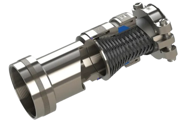
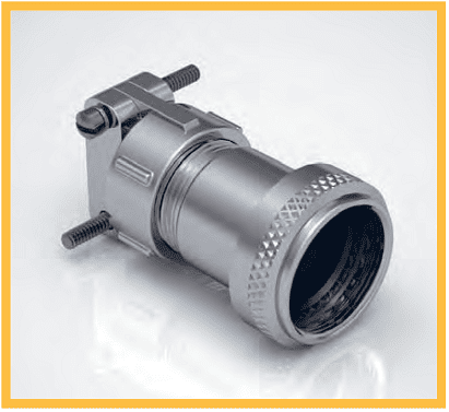
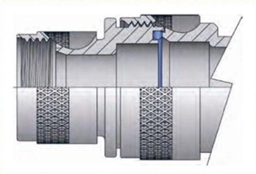
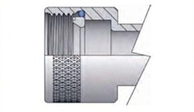
When the selected cable entry exceeds the MAX ENTRY stated in the INTERFACE TABLE, you may choose to have a type 2 assembly.
The two-piece assembly allows a large cable diameter to be maintained as close to the connector body as possible, allowing maximum continuation of screens and wire protection, whilst also providing an access point close to the connector.
To specify a type 2 assembly, place modification code -079 at the end of the part number when
ordering.
Modification Code Example: CPA461W-1410-VG0-079
To receive a standard one-piece adapter, no modification code is needed.
Wrench flats are an available option on most Compaero adapters and backshells, allowing for an easier way of tightening the coupling ring when working with reduced accessibility.
Available on straight adapters only.
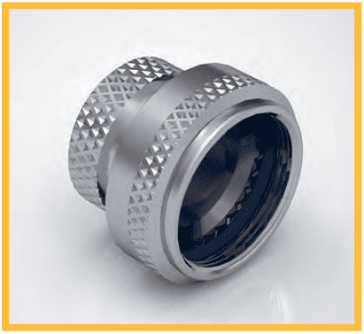
Using a spring loaded retaining ring, Compaero Seat-Lock coupling rings are a non detent way to achieve self locking. This option ensures that the accessory teeth of the connector mate properly with the teeth on the adapter or backshell by applying constant force between the two.
The Compaero Seat-Lock option is an excellent choice if an easy, economical self locking solution is required.
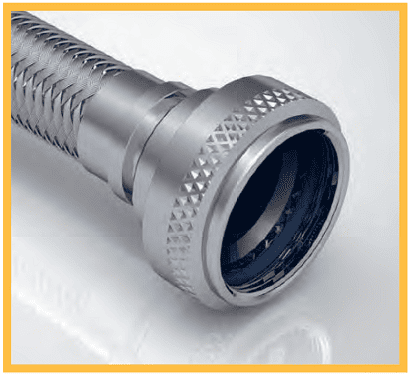
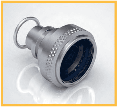
Safety wire holes can be specified on standard rotatable coupling rings for use with safety wire after installation. Safety wire ensures the coupling ring will not un-couple during shock and/or vibration. These are common on AS85049 accessories.
When this option is specified the coupling ring will have 3 equally spaced wire holes (120 degrees apart), sufficient to accommodate 0.020 inch wire.
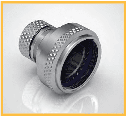
Detent style self locking features a ratcheting coupling ring using non corrosive clips located within the coupling ring.
Many AS85049 specifications specify this detent style self locking coupling ring making this one of the most popular ways of achieving a self locking adapter or backshell.
The above coupling ring options are available on most Compaero backshells and adapters.
Please contact the sales team for more information.
The below figures are provided to support operators already trained in the installation of heat shrinkable products and harnessing components. They identify the recommended torque values to be used when installing adapters onto circular electrical connectors, to consistently tighten adapters in a controlled manner.
For any questions or further instructions please contact us and we will be happy to assist you.
| SHELL SIZE |
MIL-DTL-26482 S1 MIL-DTL-38999 S1/S2 MIL-DTL-5015 Solder |
MIL-DTL-83723 | MIL-DTL-22992 MIL-DTL-5015 Crimp | MIL-DTL-38999 S3/S4 MIL-DTL-26500 | MIL-DTL-87511 MIL-DTL-26482 S2 | MIL-DTL-28840 |
|---|---|---|
| TORQUE VALUES in-lb / Nm | TORQUE VALUES in-lb / Nm | |
| 08/09 | 30-40 3.0-4.0 | 51-61 5.8-6.9 |
| 10/11 | 30-40 3.0-4.0 | 71-81 8.0-9.2 |
| 12/13 | 35-45 4.0-5.1 | 103-113 11.6-12.8 |
| 14/15 | 35-45 4.0-5.1 | 111-121 12.5-13.7 |
| 16/17 | 35-45 4.5-5.8 | 111-121 12.5-13.7 |
| 18/19 | 35-45 4.5-5.8 | 111-121 12.5-13.7 |
| 20/21 | 75-85 8.5-9.6 | 131-141 14.8-15.9 |
| 22/23 | 75-85 8.5-9.6 | 131-141 14.8-15.9 |
| 24/25 | 75-85 8.5-9.6 | 131-141 14.8-15.9 |
| 28 | 115-125 13.0-14.1 | 143-153 16.2-17.3 |
| 32 | 115-125 13.0-14.1 | 143-153 16.2-17.3 |
| 36 | 115-125 13.0-14.1 | 143-153 16.2-17.3 |
| 40 | 155-165 17.5-18.6 | 159-169 18.0-19.1 |
| 44 | 155-165 17.5-18.6 | 159-169 18.0-19.1 |
| 48 | 155-165 17.5-18.6 | 159-169 18.0-19.1 |
| CLAMP SIZE |
TORQUE VALUES in-lb / Nm |
|---|---|
| 01 | 35-40 4.0-4.5 |
| 02 | 35-40 4.0-4.5 |
| 03 | 35-55 4.0-6.2 |
| 04 | 35-55 4.0-6.2 |
| 05 | 35-55 4.0-6.2 |
| 06 | 40-60 4.5-6.8 |
| 07 | 40-60 4.5-6.8 |
| 08 | 40-60 4.5-6.8 |
| 09 | 80-100 9.0-11.3 |
| 10 | 80-100 9.0-11.3 |
| 11 | 80-100 9.0-11.3 |
| 12 | 80-100 9.0-11.3 |
| THREAD SIZE |
TORQUE VALUES in-lb / Nm |
|---|---|
| 2-56 | 1.5-2.5 0.2-0.3 |
| 4-40 | 3.5-4.5 0.4-0.5 |
| 6-32 | 5.0-7.0 0.6-0.8 |
| 8-32 | 7.0-9.0 0.8-1.0 |
| 10-32 | 9.0-11.0 1.0-1.2 |
| 1/4-20 | 11.0-13.0 1.2-1.5 |