Address
Compaero India (P) Ltd.
No. 41/773- A to A3,
RC Arcade, Ideal Lane, NH Bypass,
Padivattom, Edappally, Kochi
Ernakulam,
Kerala 682 024, India
Compaero India (P) Ltd.
No. 41/773- A to A3,
RC Arcade, Ideal Lane, NH Bypass,
Padivattom, Edappally, Kochi
Ernakulam,
Kerala 682 024, India

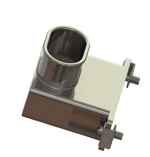
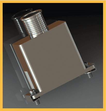
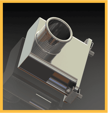
D-Subminiature connectors remain a widely adopted interconnect solution across commercial, industrial, aerospace and defense platforms, requiring reliable shielding and cable management to maintain system performance. Compaero India’s range of rectangular D-Sub backshells is designed to complement MIL-C-24308 series connectors by providing durable mechanical protection, and excellent EMI/RFI shielding for demanding operating environments. The product range encompasses straight, 45° and 90° backshell configurations with both round and elliptical cable entry options, enabling efficient cable routing and installation flexibility. Precision-machined for dimensional accuracy and long-term durability, Compaero D-Sub backshells are engineered to deliver consistent performance in applications where reliability is critical. Multiple material, finish and hardware combinations are available to accommodate specific environmental and installation requirements, allowing users to configure a backshell solution tailored to their exact application needs
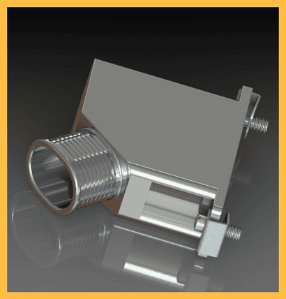
Series 46 -EMI/RFI Solid Backshell Round Entry
Series 46 -EMI/RFI Solid Backshell Round Entry
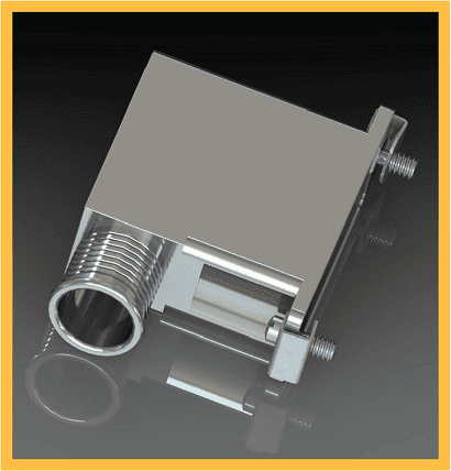
Series 46 -EMI/RFI Solid Backshell Round Entry
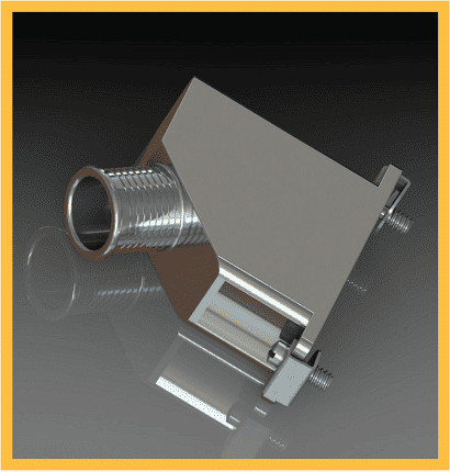
Series 46 -EMI/RFI Solid Backshell Round Entry
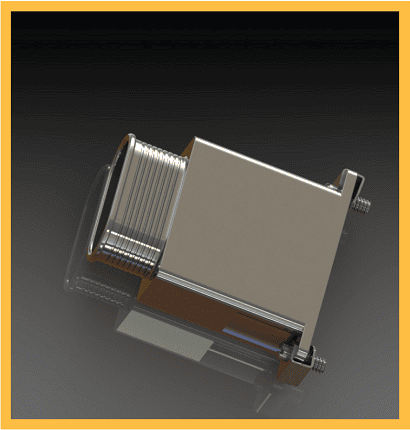
Series 46 -EMI/RFI Solid Backshell Elliptical Entry
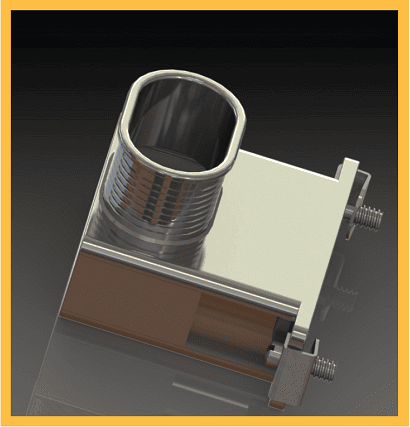
Series 46 -EMI/RFI Solid Backshell Elliptical Entry
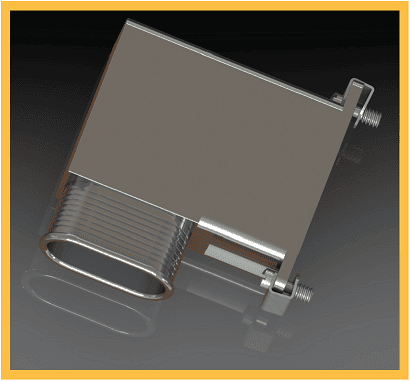
Series 46 -EMI/RFI Solid Backshell Elliptical Entry
Series 46 -EMI/RFI Solid Backshell Elliptical Entry
All Compaero backshells are available in a wide selection of material and plating combinations, from heavy duty marine applications to lightweight aerospace solutions, there is an option for almost any situation
| CODE | MIL SPEC CODE |
MATERIAL | PLATING | PROCESS | ROHS COMPLIANT |
|---|---|---|---|---|---|
| B | - | Marine Bronze | Shotblast, Nonreflective | 1000 Hour Salt Spray, Conductive -65 to +200°C | Yes |
| C | A | Aluminum | Anodize, Black | AMS-A-8625 Type II Class 2, 336 Hour Salt Spray, Non-Conductive -65 to +175°C | Yes |
| F | N, F | Aluminum | Electroless Nickel | AMS-C-26074 Class 4 Grade B; ASTM-B-733, SC 2, Type IV, 48 Hour Salt Spray, Conductive -65 to +200°C | Yes |
| G | - | Aluminum | Anodize, Hardcoat, Black | AMS-A-8625 Type III, Class 2, .001" thick, 336 Hour Salt Spray, Non-Conductive -65 to +200°C | Yes |
| KB | B | Stainless Steel | Cadmium, Black | SAE-AMS-QQ-P-416 Type II Class 3, 1000 Hour Salt Spray, Conductive -65 to +175°C | No |
| K | S | Stainless Steel | Passivate | SAE-AMS-SAE-AMS-QQ-P-35 Type V , 1000 Hour Salt Spray, Conductive -65 to +200°C | Yes |
| KL | - | Stainless Steel | Electrodeposited Nickel | SAE-AMS-QQ-N-290 Class 1 Grade F, 1000 Hour Salt Spray, Conductive -65 to +200°C | Yes |
| TR | - | Aluminum | Zinc-Nickel, Black | ASTM B841 Grade 5 over electroless nickel, 500 Hour Salt Spray, Conductive -65 to +175°C | Yes |
| T | - | Aluminum | Zinc-Nickel, Black | ASTM B841 Grade 5 over electroless nickel, 1000 Hour Salt Spray, Conductive -65 to +175°C | No |
| W | W | Aluminum | Cadmium, Olive Drab | SAE-AMS-QQ-P-416 Type II Class 2 over electroless nickel, 1000 Hour Salt Spray, Conductive -65 to +175°C | No |
| X | - | Aluminum | Unplated | - | Yes |
| Y | - | Aluminum | Zinc-Cobalt, Olive Drab | ASTM B 840 Grade 6 Type D over electroless nickel, 350 Hour Salt Spray, Conductive -65 to +175°C | Yes |
| ZN | - | Aluminum | Zinc-Nickel, Olive Drab | ASTM B841 Grade 5 over electroless nickel, 1000 Hour Salt Spray, Conductive -65 to +175°C | No |
| Z | - | Aluminum | Zinc-Cobalt, Black | ASTM B 840 Grade 6 Type D over electroless nickel, 350 Hour Salt Spray, Conductive -65 to +175°C | Yes |
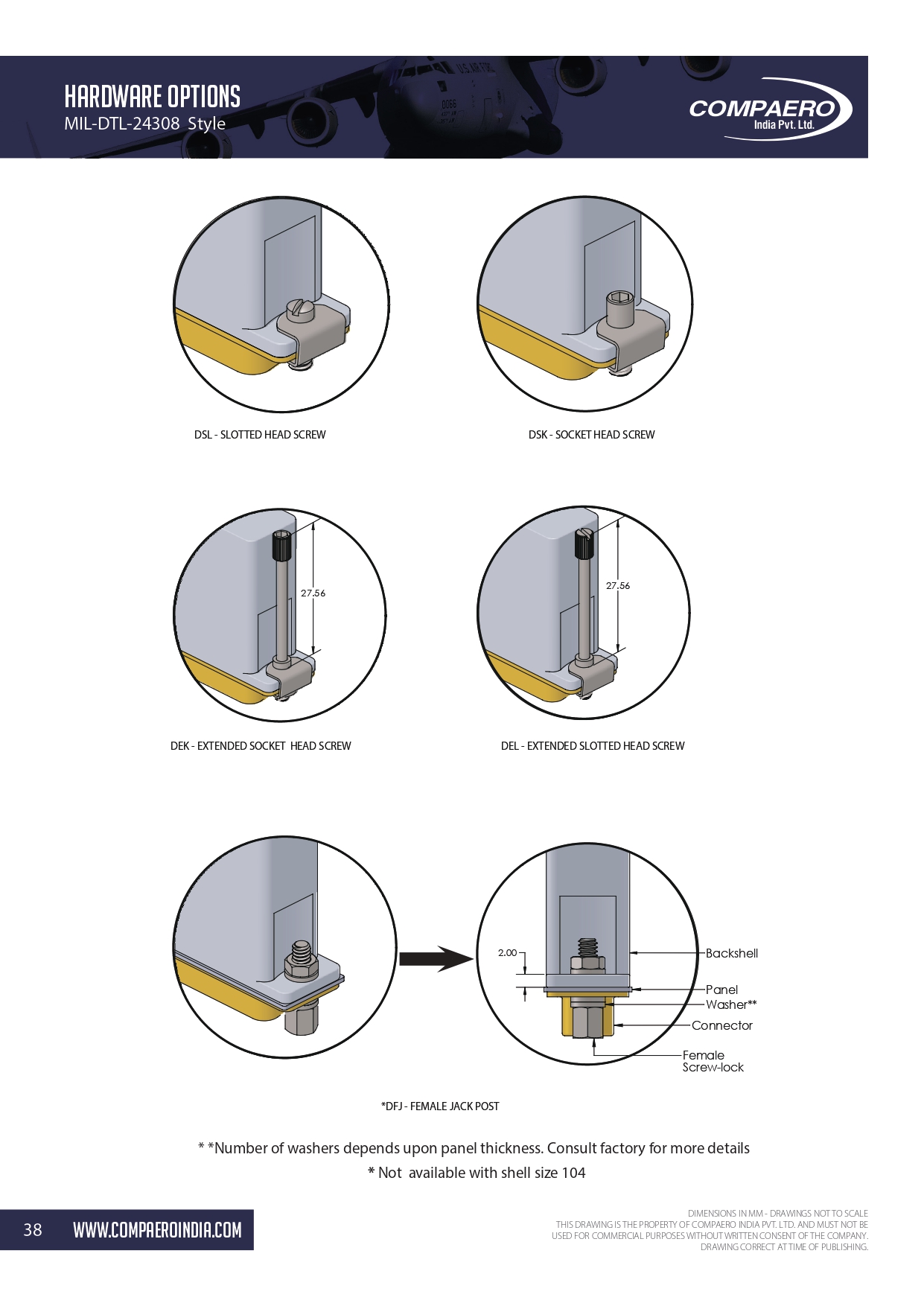
Compaero offers a range of hardware options designed to meet various installation and application requirements.